


 1Likes
Xray T1FK05
 05-26-2005, 04:45 PM
#2446
Tech Fanatic
Haha....nice...I can pick your brains about the fk05 now!
I've been in and out ...of rc for a while as well! This time i'm also back into electric again. Will you be going to RCCAR at all?
BTW any of you know if the TRF evo4 shocks will fit the fk05? I just bought a new set....if anything I'll let you guys know...haha...
I've been in and out ...of rc for a while as well! This time i'm also back into electric again. Will you be going to RCCAR at all?
BTW any of you know if the TRF evo4 shocks will fit the fk05? I just bought a new set....if anything I'll let you guys know...haha...
 05-26-2005, 05:10 PM
#2447

Originally Posted by loosenut
Haha....nice...I can pick your brains about the fk05 now!
I've been in and out ...of rc for a while as well! This time i'm also back into electric again. Will you be going to RCCAR at all?
BTW any of you know if the TRF evo4 shocks will fit the fk05? I just bought a new set....if anything I'll let you guys know...haha...
I've been in and out ...of rc for a while as well! This time i'm also back into electric again. Will you be going to RCCAR at all?
BTW any of you know if the TRF evo4 shocks will fit the fk05? I just bought a new set....if anything I'll let you guys know...haha...
05-26-2005, 05:21 PM
#2448
Tech Fanatic
Harsh guy,
Can you elaborate a little - what extra part...from tamiya or from xray? I'll see if I can find your post..if you know which page number that would be awesome! Thx
G
Can you elaborate a little - what extra part...from tamiya or from xray? I'll see if I can find your post..if you know which page number that would be awesome! Thx
G
05-26-2005, 05:24 PM
#2449
Tech Fanatic
found it! Page 72
What you wrote:
Then you'll need 1 of these xray ball joints:
https://www.ssl-stormerhobbies.com/...pl?pn=XRA303220
And one of these xray ball ends (unless you want to try and take out of your xray shocks):
https://www.ssl-stormerhobbies.com/...pl?pn=XRA303240
...I used the xray aluminum collars as the Tamiya ones where "cheezy"
You will also need 4 - 3 mm lock nuts
On the ball connectors, the shocks come with gold ones, so the colored ones above are just if you want to "color coordinate",
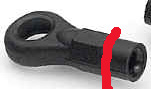
OK, now for the front shocks, you will use 2 of the ball connectors with 3 mm nuts for the top into the shock tower, and 2 of the Xray ball joints with the ball ends put in them on the shock shaft, you'll need to cut the ball end just above the "nut" looking thingee ...where this red line is:
This will go on the bottom with a 3mmx10mm screw into the arm, I made the from shocks 65mm ling
Now the rear shocks, you'll use the short connectors in the tamiya set for the bottom of the shock, you will use 2 of the ball connectors with 3 mm nuts for the top into the shock tower, for the arm you'll screw 2 of the ball connectors into the arms, I made the rear shocks 61.5mm long
xray springs work perfectly
I'm getting a set of these:
http://www2.towerhobbies.com/cgi-bi...p?&I=LXETK6&P=7
That I *think* should work instead of the ball connectors were I can put a 3mm screw through them (the ball conectors make me "nervous")
What you wrote:
Then you'll need 1 of these xray ball joints:
https://www.ssl-stormerhobbies.com/...pl?pn=XRA303220
And one of these xray ball ends (unless you want to try and take out of your xray shocks):
https://www.ssl-stormerhobbies.com/...pl?pn=XRA303240
...I used the xray aluminum collars as the Tamiya ones where "cheezy"
You will also need 4 - 3 mm lock nuts
On the ball connectors, the shocks come with gold ones, so the colored ones above are just if you want to "color coordinate",
OK, now for the front shocks, you will use 2 of the ball connectors with 3 mm nuts for the top into the shock tower, and 2 of the Xray ball joints with the ball ends put in them on the shock shaft, you'll need to cut the ball end just above the "nut" looking thingee ...where this red line is:
This will go on the bottom with a 3mmx10mm screw into the arm, I made the from shocks 65mm ling
Now the rear shocks, you'll use the short connectors in the tamiya set for the bottom of the shock, you will use 2 of the ball connectors with 3 mm nuts for the top into the shock tower, for the arm you'll screw 2 of the ball connectors into the arms, I made the rear shocks 61.5mm long
xray springs work perfectly
I'm getting a set of these:
http://www2.towerhobbies.com/cgi-bi...p?&I=LXETK6&P=7
That I *think* should work instead of the ball connectors were I can put a 3mm screw through them (the ball conectors make me "nervous")
05-26-2005, 06:14 PM
#2450
Originally Posted by loosenut
found it! Page 72
What you wrote:
Then you'll need 1 of these xray ball joints:
https://www.ssl-stormerhobbies.com/...pl?pn=XRA303220
And one of these xray ball ends (unless you want to try and take out of your xray shocks):
https://www.ssl-stormerhobbies.com/...pl?pn=XRA303240
...I used the xray aluminum collars as the Tamiya ones where "cheezy"
You will also need 4 - 3 mm lock nuts
On the ball connectors, the shocks come with gold ones, so the colored ones above are just if you want to "color coordinate",
OK, now for the front shocks, you will use 2 of the ball connectors with 3 mm nuts for the top into the shock tower, and 2 of the Xray ball joints with the ball ends put in them on the shock shaft, you'll need to cut the ball end just above the "nut" looking thingee ...where this red line is:
This will go on the bottom with a 3mmx10mm screw into the arm, I made the from shocks 65mm ling
Now the rear shocks, you'll use the short connectors in the tamiya set for the bottom of the shock, you will use 2 of the ball connectors with 3 mm nuts for the top into the shock tower, for the arm you'll screw 2 of the ball connectors into the arms, I made the rear shocks 61.5mm long
xray springs work perfectly
I'm getting a set of these:
http://www2.towerhobbies.com/cgi-bi...p?&I=LXETK6&P=7
That I *think* should work instead of the ball connectors were I can put a 3mm screw through them (the ball conectors make me "nervous")
I have also used some General Silicone cone washers to allow the shocks to move freely now that I'm using the ball nuts and driving a screw thru them:
 05-26-2005, 10:07 PM
#2451
Tech Fanatic
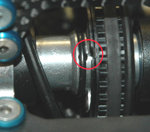
Question guys....the instruction says that there is a hole on the pulley that should line up with the hole on the axle (multi-diff assembly) - I don't see no hole on the pulley! Please advise...thx.
Gary
Gary
05-26-2005, 10:13 PM
#2452
Tech Regular
iTrader: (12)
Originally Posted by loosenut
Question guys....the instruction says that there is a hole on the pulley that should line up with the hole on the axle (multi-diff assembly) - I don't see no hole on the pulley! Please advise...thx.
Gary
Gary
 The hole does look like it sits far enough out, that you can get the pin in w/o contacting the pulley.
05-27-2005, 04:15 AM
The hole does look like it sits far enough out, that you can get the pin in w/o contacting the pulley.
05-27-2005, 04:15 AM
#2453
Originally Posted by loosenut
Question guys....the instruction says that there is a hole on the pulley that should line up with the hole on the axle (multi-diff assembly) - I don't see no hole on the pulley! Please advise...thx.
Gary
Gary
 05-27-2005, 10:03 AM
#2454
Tech Fanatic
Dude...I'm serious...I do not have that hole or indent on my pulley!!!!! WTF....
05-27-2005, 11:01 AM
#2455
Tech Fanatic
Yep, I think Xray revised their design...the pin hole is far out enough where you can get to it with out removing the pulley.
G
G
05-27-2005, 03:48 PM
#2457
Originally Posted by loosenut
Yep, I think Xray revised their design...the pin hole is far out enough where you can get to it with out removing the pulley.
G
G
 05-27-2005, 08:11 PM
#2458
Been getting PM's about the links not working on the cut and paste of my one post re: Tamiya shocks, so here's the info again, it was actually a cut and paste of an email I had sent:
...since that email I have gone to using the ball nuts mentioned at the end of the email with the general silicone cone washers, aditionally I have replaced both cars tamiya shocks with their new "special edition":
http://cgi.ebay.com/ws/eBayISAPI.dll...sPageName=WDVW
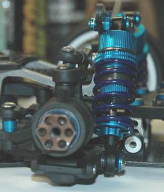
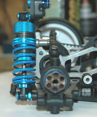
So now everything looks like so ...
front:
rear:
OK, here's what you need ---
For Blue:
Shocks:
http://www2.towerhobbies.com/cgi-bin/wti0001p?&I=LXFSA3&P=7
Ball Connectors:
http://www2.towerhobbies.com/cgi-bin/wti0001p?&I=LXFSC8&P=7
For Red:
Shocks:
http://www2.towerhobbies.com/cgi-bin/wti0001p?&I=LXFSA4&P=7
Ball Connectors:
http://www2.towerhobbies.com/cgi-bin/wti0001p?&I=LXFSC9&P=7
Then you'll need 1 of these xray ball joints (Billy may have):
https://www.ssl-stormerhobbies.com/cgi-bin/seekpart.pl?pn=XRA303220
And one of these xray ball ends (Billy may have -- unless you want to try and take out of your xray shocks:
https://www.ssl-stormerhobbies.com/cgi-bin/seekpart.pl?pn=XRA303240
...I used the xray aluminum collars as the Tamiya ones where "cheezy"
You will also need 4 - 3 mm lock nuts (you can get @ Billy's or Ace Hardware in Roseville)
On the ball connectors, the shocks come with gold ones, so the colored ones above are just if you want to "color coordinate",
OK, now for the front shocks, you will use 2 of the ball connectors with 3 mm nuts for the top into the shock tower, and 2 of the Xray ball joints with the ball ends put in them on the shock shaft, you'll need to cut the ball end just above the "nut" looking thingee ...where this red line is:
This will go on the bottom with a 3mmx10mm screw into the arm, I made the from shocks 65mm ling
Now the rear shocks, you'll use the short connectors in the tamiya set for the bottom of the shock, you will use 2 of the ball connectors with 3 mm nuts for the top into the shock tower, for the arm you'll screw 2 of the ball connectors into the arms, I made the rear shocks 61.5mm long
xray springs work perfectly
I'm getting a set of these:
http://www2.towerhobbies.com/cgi-bin/wti0001p?&I=LXETK6&P=7
That I *think* should work instead of the ball connectors were I can put a 3mm screw through them (the ball conectors make me "nervous")
http://cgi.ebay.com/ws/eBayISAPI.dll...sPageName=WDVW
So now everything looks like so ...
front:
rear:
05-27-2005, 08:31 PM
#2459
Tech Fanatic
I'm still confused...you used ball nut and then screwed a counter sunk screw thru it? Looks that way on the pics...also do you have a link for the GS washers? Where does it sit on the ball nut? Thx. bro!
05-27-2005, 10:34 PM
#2460
All you have to do to use the Tamiya shocks is screw the xray ball cup onto the Tamiya shock shaft, and use the normal xray hardway. And for the top of the shock just use a normal Tamiya shock ball joint. Thats it there is no need to do any cutting.